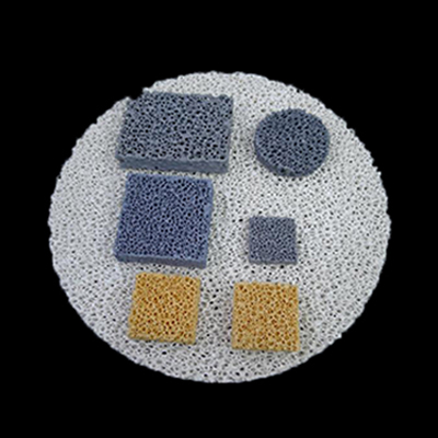
How do I place a Foam ceramic filter?
Foam ceramic filterFoam ceramic filters are placed in the pouring system: lower sprue, cross sprue, inner sprue, pouring cup. Principles of use:
(1) The closer the placement position is to the casting cavity, the better, and the lower the probability of secondary oxidation;
(2) The design of the pouring system is simple, and other slag blocking measures are not considered, which can improve the utilization rate of sand mold and process productivity;
(3) The working area of the filter should be 4~6 times of the blocking section of the gating system to ensure that the pouring speed is not affected;
(4) Select the corresponding filter according to the type of casting alloy and pouring temperature, and shall not over-temperature;
(5) Choose the right pore size to really play a filtering role;
(6) The pouring speed cannot be controlled by the filter.Select the pore size of theFoam ceramic filter。
The pore size selection of the foam ceramic filter should be determined according to the nature of the metal liquid to be filtered. Filters with large pore size should be selected for filtering metal liquids with viscous, poor fluidity and large impurity particles; Filters with good fluidity and thin molten metal should choose filters with small pore size. The pore size is too large to be filtered; Having a small pore size can lead to premature clogging of the filter, resulting in termination of filtration or even failure to filter, which is especially important for ductile iron.
The general principle of selecting the pore size of theFoam ceramic filter:
(1) Ductile iron castings, large gray iron castings, and steel castings can be used for hole size specifications of 10ppi;
(2) Malleable iron castings, small gray iron castings, non-ferrous alloy castings, small gray castings, non-ferrous alloy castings;
(3) The hole size specification of copper alloy castings and aluminum alloy castings is 30ppi.

